I'm currently putting together a new project where I'm attempting to automate the control of an old RC Car. I've ripped out the original guts except for the the drive motor and steer motor. After numerous attempts at a DIY motor controller for the drive motor (and popping through transistors like popcorn), I've come to the conclusion that this motor needed a driver who could handle the spike currents without melting under pressure. Here is a list of all the parts that will be going into this project, and later I will provide updates on my progress.
Parts:
1. Original RC Chasis (including suspension and wheels/tires).
2. Original RC 7.2V Battery Packs (2)
3. Original rear-wheel drive motor (specs unknown except that it draws 3.5A current running, and 15A stall).
4. Orignal steering motor + original feedback potentiometer (specs also unkown)
5. Boarduino (Atmega 328) controller
6. 18v15 Pololu Motor Driver (to properly drive the rear motor)
7. Dual AxisCompass Module - HMC6352
8. Xbee Pro 60mW U.FL modules + antenna (2): for wireless comunication
9. A few 2n2907/2n2222 BJTs for driving the steering motor
Wednesday, August 4, 2010
Sunday, April 25, 2010
Light Follower - 2 Axis
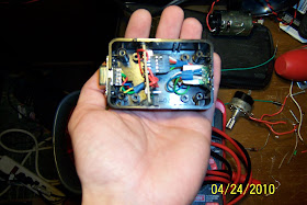
Here it is - My rendition of a 2-axis light follower. I went ahead and clipped the IR Cam from the wiimote to cut down on weight. I put the camera along with the required oscillator in a project box (from radio shack). I also included an LED on the box; it lights up when light is seen by the camera. A serial port is used to connect the box to the microcontroller.
Here are some Pictures:
Here is a video:
Here is a link to the code:
Wednesday, March 17, 2010
Nintendo nunchucks as Orientation Sensors
My senior design project was to make a wirelessly controlled robotic arm, that mimics human arm movements. The closest we got was the movement of a shoulder joint and an elbow joint at a very high accuracy and low time delay.
I made a sensor system out of 2 Wii Nunchucks, an Arduino and some external circuitry to switch between nunchuck sensor reading. At a deadline of one of our presentations, a plastic gear from our arm had chipped some of its teeth so we weren't able to give motion demos. I whipped up a program using Processing (processing.org) to communicate with the Arduino and move a 3D simulation of an arm based on the sensor outputs.
I thought I'd share a few screenshots of the program. I'll have both the Arduino code, and processing code up soon.
Processing is a great program for doing graphical manipulations. It can also compile code to execuatable files.
Wiimote light follower with servo
Everybody is familiar with the infamous Wiimote. When I look at it, I think about all the useful sensors/gadgets that this little 40$ package (new) comes with. Recently I've been playing with the IR Camera (It's really just a light sensing camera with an IR Filter).This particular camera is a standalone module that outputs coordinates of the 4 brightest "images", all via I2C communication.
I've only seen hacks with the Wiimote cam where the camera is desoldered/removed from the Wiimote. However, at 40$ a pop that seemed like a waste of a perfectly good Wiimote. Instead of removing the cam, I only made 1 small modification, which was drilling a very tiny hole near the camera and soldering a connection to it's "Clock" pin (which needs to be a 24MHz sine wave to replace the internal oscillator). Once you have this done, all you need to do is plug a cord into the Wiimote peripheral port to use anything on its I2C bus.
Moving on, I attached the Wiimote on a homemade stand that was fixed onto a continuous-rotation servo motor (servo without feedback). Add a little duct tape, and that servo isn't moving for at least an hour.
Using an IR Camera library already created (thanks to Hobley – http://www.stephenhobley.com/), I used an Arduino to receive points from the camera and follow the 1st object (light source) that's noticed.
The code can be found here:
http://www.youtube.com/watch?v=Nj7UqjP-z6U
Monday, March 15, 2010
Two Wii Nunchucks with one arduino
In the midst of a senior design project, it was decided that we wanted to use 2 Wii Nunchucks as accelerometers to measure orientation of a human arm ( 1 for the upper arm and 1 for the forearm). In understanding I2C communication, there is no way to use 2 Nunchucks on the same I2C bus without some sort of external circuitry. (All nunchucks have the same slave address, leaving nothing to distinguish between the two when attempting to receive data).
I drew up a simple and cheap solution to interface two (or more) Wii Nunchucks on the same I2C bus. This is useful for projects that require multiple accelerometers at a cheap price.
Here is all you will need:
2 npn switching transistors (I used 2N3904)
2 current limiting resistors (I used 200 Ohm)
Just connect all nunchuck Power (PWR), Clock (SCL), and Ground (GND) wires to the same corresponding spots on your microcontroller. The microcontroller's SDL can be connected to the outputs of both transistors.
Programming notes:
In order to perform a read, all you have to do is set the pin of the corresponding transistor to HIGH (5v in our case), write/read to the I2C bus, then set that pin to LOW (0v)to disconnect that nunchuck from the bus. Also, during start up you must initialize each nunchuck individually in order to operate both nunchucks correctly.
Good luck,
B Dwyer (aka: johnnyonthespot)